Tuesday, December 19, 2023

Camshaft IV

I know it's been a while... again... but I did finish this!

Once I got the cam timing set, it was just a matter of reassembly.  But I did a little extra cleanup on the intake manifold too.  

Per Vizard's book:

Being aluminum and having a spare made this an easy job.


I've already done all the other tricks rto the carb bodies themselves.  Once of these days I need to have a flow test done.

Okay, on to reassembly!

So I'd love to be able to say that was the end of the saga.  But you know the answer to that.

The first problem showed up when I went to start up.  I couldn't get her to start.  I tried checking timing and fuel, but no dice.

Then, I heard a horrible squealing noise when I went to start.  I thought I had done Something Really bad inside the engine.  Fortunately, it wasn't that bad.  The starter bendix hung up and stayed engaged.


I got it unstuck for the time being, but I did end up replacing it with a high torque starter (which works great!) from a 1989 Isuzu Trooper II.  It is a direct fit replacement with no modification required.

Finally, I get the timing set right and she started!  She sounded great and oil pressure came up immediately... but I noticed that the oil pressure was low, like 50psi instead of the 70-80 I expected.  I finished the 20 minute break-in and shut her down, and went to think.  And I had a horrible thought.  I went to look at the main bearings I removed.  The back of the bearing read ".010".  I put in standard size bearings.

Aw, come on!

So that meant I had to do the job over again, except for removing the cam from the block.  It didn't take a ton of time, and I had the whole 'swap bearings in block' routine down pretty well.  It just hurt my pride to have to disassemble what I had spent so much time painfully reassembling.

In the end, post-swap oil pressure came up to 75psi and stayed there.  After another break-in period, I went for a drive.  And wow.  Gidget's got some guts now!  She pulls strongly and really takes off at 3000 RPM.

I've put about 500 miles on her since I finished the work (and went to the 2023 BWOG!), and she still runs amazingly well.  Oil pressure comes up immediately and I have 60psi at hot idle.  She is a little clattery until she warms up, but the sounds of a self destructing camshaft is gone.

And you might notice a little extra bling... she's worth it.


Life is good once again. 

More... »

Monday, August 21, 2023

Camshaft Replacement III: The Search for More Power

LLAP...

I'm getting there.  I was just waiting for this.


This little bugger cost way too much.  But I had to have it, to set up the cam properly.  It is an 'offset key' that shifts the engagement of the camshaft by 2 degrees.

Anyhow, that's done.  I installed the key and rechecked the timing as I described in my last post.  This time, I got (61 + 153) = 214 / 2 = 107.  That's spot on. I'm within a degree and that's good enough for what I can do.

I buttoned up the sump, installed the oil thrower and timing cover and crank pulley, and the bottom end is complete.


And I cleaned, too!

After a short celebratory rest, I turned my attention to the head.  My plan was to polish the combustion chambers, and port and polish the exhaust ports.  I intend to leave the intake ports alone because they already match the diameter of the intake manifold, and I have read that a little 'swirl' (turbulence) is helpful to mix up the intake charge.  Maybe I'm full of it, but that's my story and I'm sticking with it.

Here's the head before I did anything.


Nothing special, right?  Right.

All I did was spend a lot of time with near-infinite patience to gently polish the combustion chamber surfaces to be as smooth as I could get without going mad.  I think I did okay.  I used a small tapered grinding stone and some cylinder and cone-shaped sanding tubes.  I think I got away with it.  I did not appreciably increase the size of the combustion chamber.  Here's a comparison:

And the final result:

Who knows if it will help things.

The real gain I intended to reap was in the exhaust ports.  The port openings are significantly smaller than the manifold's openings as evidenced by the buildup on the manifold gasket.  So I got to work with that tapered grinding stone.  I managed to open things up quite a bit without screwing things up.  After the grinding stone, I used those tapered cylinders up to 240 grit to smooth things out.  Exhaust is one area where you do NOT want swirl; it will slow the exiting gases and you want them to leave quickly. 

Here's a before and after comparison.  The blue marks are where the gasket is larger than the port (and mot matched), and that's what I opened up.

I think that's a lot.  I had to be careful not to break through to the pushrod holes, because that would have been A Bad Thing.

Here's the finished product.


I painted the head after cleaning all the gunk out from the porting process.

All that remains is to assemble the valves to the head and start putting big pieces together!
More... »

Wednesday, August 16, 2023

Camshaft (And Other Things) Part Deux

Well, I know I said I'd have it all back together in this episode, but nah.  I did make some progress.

Having extracted the cam and lifters, I took a closer look.  Not good.

I decided that since I was already this far, I'd take a look at the main and rod bearings to judge if they had been worn due to my little cam problem and the lack of oil pressure at startup.  I pulled the center main bearing, and while they aren't "bad", they aren't great either.  I see a little bit of stuff.  It could be much worse.

You can see some wear in a couple of spots.  The crank journal looks okay, though.

The $64,000 question was how I was going to get the bearing out with the crankshaft in place.  I tried a popsicle stick, but it didn't have enough flexibility to be able to push the bearing shell all the way around.  But I did have bearing shells... the ones I was removing!  So I cut one down carefully and filed the end.  This gave me about 1/4" of room to be able to push on the shell (with a wooden dowel) and spin the old shell right out.  It worked a treat.  Then, I lubed up the journal and bearing and rotated the new bearing into position, which pushed my cut-down bearing shell back out and into my hand.

I was only able to get to the front and center main bearings.  The rear main bearing cap is trapped by the rear plate where the transmission is, and I wasn't able to maneuver it out of the way.  So that bearing has to stay until I pull the engine someday.  But given the other two bearings weren't significantly worn, I'm gonna have to be okay with that.

Replacing the big end (rod) bearings was pretty easy.  That's as simple as removing the cap, pushing the piston and rod up enough to move the crank out of the way, and popping the bearing shell out.  Putting it back is about as easy.  It's not THAT easy to do while lying on your back, but it wasn't bad.

Once they were all replaced, I gave them a once-over and wasn't terribly disappointed.  There is wear, more than I like, but there are no streaks or gouges indicating metal was trapped in the bearings.  So I feel better.  Hopefully solving my oil prime issue will minimize this problem in the future.


Once the bearings were in place, I bolted up and tightened(!) the oil pickup.

I then cleaned the pistons and bores to remove the excessive carbon buildup I found.

Ooh, shiny!

With the bottom end basically complete, it was time to time the camshaft.  "Timing a camshaft" or "degreeing a camshaft" means determining the angles at which the valves open and close and making sure they match the manufacturer's specifications and/or recommendations.  For the cam I installed, Mini Spares recommends the LCA (Lobe Centerline Angle, or the spot where the intake valve is fully open at maximum lift) to be 107 degrees.  Engines typically have this value between 102 and 110 degrees.  An earlier opening (retarded, which ironically is a larger number) gives a little more push at lower revs, and a later opening (advanced, opening earlier) moves the power band upward.  But there are limits, so knowing what the manufacturer wants matters.

The way to degree a camshaft is relatively straightforward after you do this a couple of times:

  1. Put the #1 piston roughly at TDC so you can install the timing gears.
  2. Install the timing gears, with the manufacturer's timing marks as close to aligned as possible. 
    Usually there are indentations on each gear, so it's also known as 'lining up the dots'.


  3. Install a degree wheel.  A degree wheel provides the angles at which events (like a valve opening) occur relative to TDC.
  4. Install a pointer and line it up so that the pointer points to the degree wheel at TDC (0 degrees).
  5. Find "true TDC".  To find TDC, you need to figure out exactly when the piston is moving from its upward to its downward motion.  To do this with the cylinder head removed, you need a dial indicator that measures in small increments and a stand to hold it securely in place.  Here, I am already setting it up to measure valve lift.  To measure TDC, get the indicator's pointer to rest lightly upon the #1 piston and zero out the dial.


    • Rotate the crankshaft back and forth until you see the maximum value for the piston's height.  Zero the dial at that value.
    • Rotate the crankshaft back until the indicator shows a drop of some value (like -.020") and mark the value on the degree wheel.
    • Rotate the crankshaft forward until the same reading is found, and mark the value.
    • Split the difference between the two values.  For example, if the values are 6 and -8, the total would be (6 + (-8)) = -2, and the true value would be half that at -1 degrees.
    • Adjust the degree wheel.  In this case, I adjusted it back by one degree.  When I brought the crankshaft back to TDC, the pointer showed 0.
  6. Once TDC is found, find the LCA.  This is done by finding where the #1 intake valve reaches maximum lift.  To find maximum lift, you need a pushrod installed in the lifter hole for the #1 intake valve and your dial indicator set up like the picture above.  The pointer of the indicator rests in the cup of the pushrod.
    • Rotate the crankshaft until the indicator reaches its lowest reading.  This happens to be when the valve is closed.  Zero the dial.
    • Rotate the crankshaft clockwise and watch the dial spin until it reaches its maximum value.  Note this as your intake valve lift and compare to spec.  My spec indicated .264" of lift, and I measured exactly .264".  Zero the dial and note the reading on the degree wheel for reference.  This will be close to the final value, but not exact.  There are a couple of degrees where the lift value won't change, but the angle will. 
    • Rotate the crankshaft counterclockwise past -0.050" on the dial, and then forward until the dial reads -0.050".  Since the engine turns clockwise, rotating backward, then forward removes any slop from the timing chain.  Mark the value on the degree wheel.
    • Rotate the crankshaft forward until the dial reads +0.050".  Mark the value.
    • Add the numbers and divide by 2.  In my case, the values were 58 and 151.  My result is (58 + 151) = 209 / 2 = 104.5.  That is the true LCA as measured.  My initial rough reading was 105, so it was pretty close.
    • You probably want to do this a couple of times to compare values.
  7. Since I am looking for 107 degrees as my LCA value, I need an offset key which allows the camshaft timing gear to be rotated a tiny bit to either retard or advance the timing.  You can get offset keys in degree increments.  Since I can't get a half-degree of offset, I went with a 2 degree offset key.  That will retard the timing just a tad, which moves my powerband down a bit and that's where I want it.

And that's as far as I got.  I'm waiting for the offset key.  Once I have it, I'll install it and retime to verify I am at an LCA of 107-ish degrees.  Then I'll bolt in the cam timing gear, button up the sump, and reinstall the oil thrower, timing chain cover and crank pulley.  That will finish off the bottom end rebuild.

Then, I'll move to the top end...
More... »

Saturday, July 22, 2023

Camshaft (And Other Things) Part 1

I've been hearing some 'ticking' noises from Gidget's powerplant for a while, and so I stopped driving her regularly last fall after the 2023 BWOG.  In fact, I've only driven her about 200 miles since then.  I decided that today was the day I'd get around to doing something about it.

I figured the noise was coming from something related to the head, as that's where I was hearing it the most.  It sounded like your regular old valve train noise, but only with one cylinder a bit louder.  I checked valve lash and it was fine, so I figured something was up.

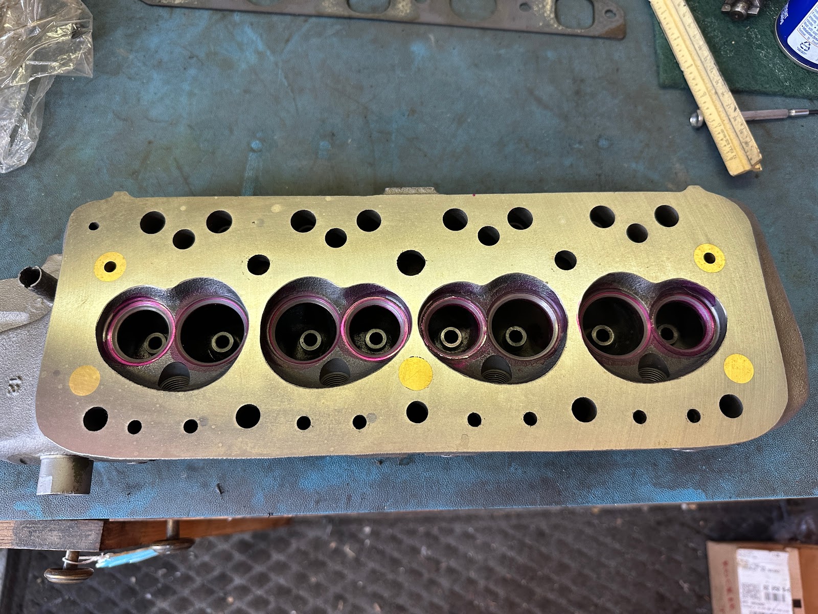
So I pulled the head.  I knew the valve guides were iffy and the valve seats were not hardened, and I wanted that fixed anyhow.  That went well.  I'm going to do some porting work a la David Vizard, so I took it apart.  And I got new tools.


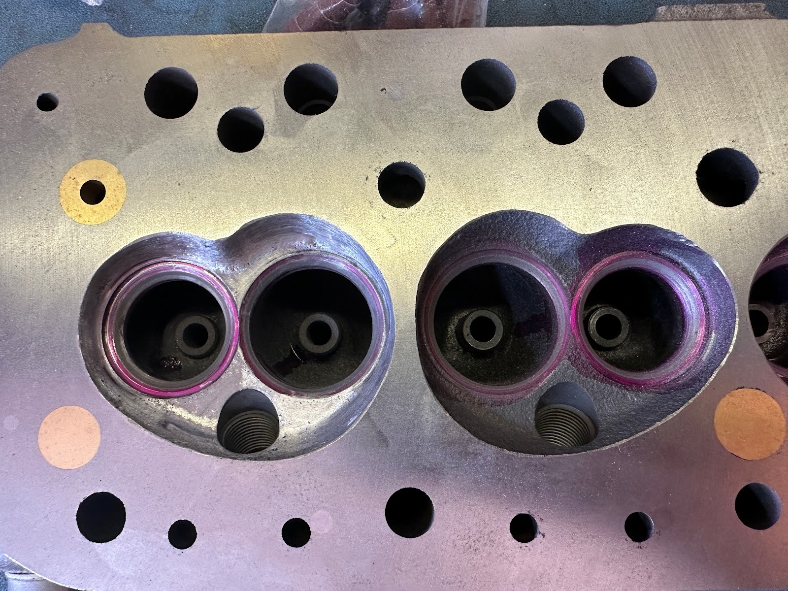
I won't do anything radical; just a little cleanup work at the exhaust ports and some smoothing of the combustion chamber.  But it looks so much better and the new iron (old-school!) guides are in place. 

While I was waiting, I said to myself, "Self... this is a great time to do a couple of other things."  I had wanted a new, more aggressive camshaft profile for a while now and I also wanted to look inside the oil pan to see why my oil pressure might be wonky at startup.  When she starts, she doesn't hold "prime" and has to turn over a few too many times to build pressure, which is then not consistent until she warms up.  That's not right.

So I got started.  First things first - I removed the grille, so I could remove the radiator.  It was an easy job.  Too easy... as I would be paid back for later.

(This will also be an excellent opportunity to clean up the engine bay.)

After removing the fan and pulley from the water pump, I discovered a major problem.  How was I going to get that pulley off the crankshaft?

There is a crossmember that supports the steering rack, and there is practically no clearance for the pulley to maneuvered out.  I pondered this for a while, and decided that I could lift the engine on a jack if I removed the motor mount bolts.  Again, this was a too-easy job and they came out in minutes.  I lifted the engine up, and found I could not raise it enough to get the pulley to clear.  I have a Datsun 5-speed conversion kit installed, and the bellhousing does not clear the heater tray.

See what I mean?  It was too easy.  Now I would pay.

I sat and stared at this problem for a good half hour, trying to figure out how I'd get an inch of clearance to be able to pull that pulley off.  Well, at least I could get to the nut, once I moved the oil cooler out of the way enough to get an impact wrench in there.  (The nut is 1 5/16", and I have one of those sockets).  With a coupler, I had clearance, Clarence.  The nut came off easily, but not too easily as one would expect.

At that point, I was well and truly stuck.  In desperation, I thought I could perhaps remove the transmission mount and slide the engine back somewhat.  The bad news there was twofold: 1) The mount is bolted to the transmission in places I cannot reach, and 2) even if I did so, I'd only get 1/2 of clearance.  Being out of options, I decided to unbolt the mount from the body and slide the whole thing back that 1/2".

But happy times were ahead.  I lifted the engine up again as far as I could, and tried to remove the pulley... and it came out!

Holy... um, something, Batman!

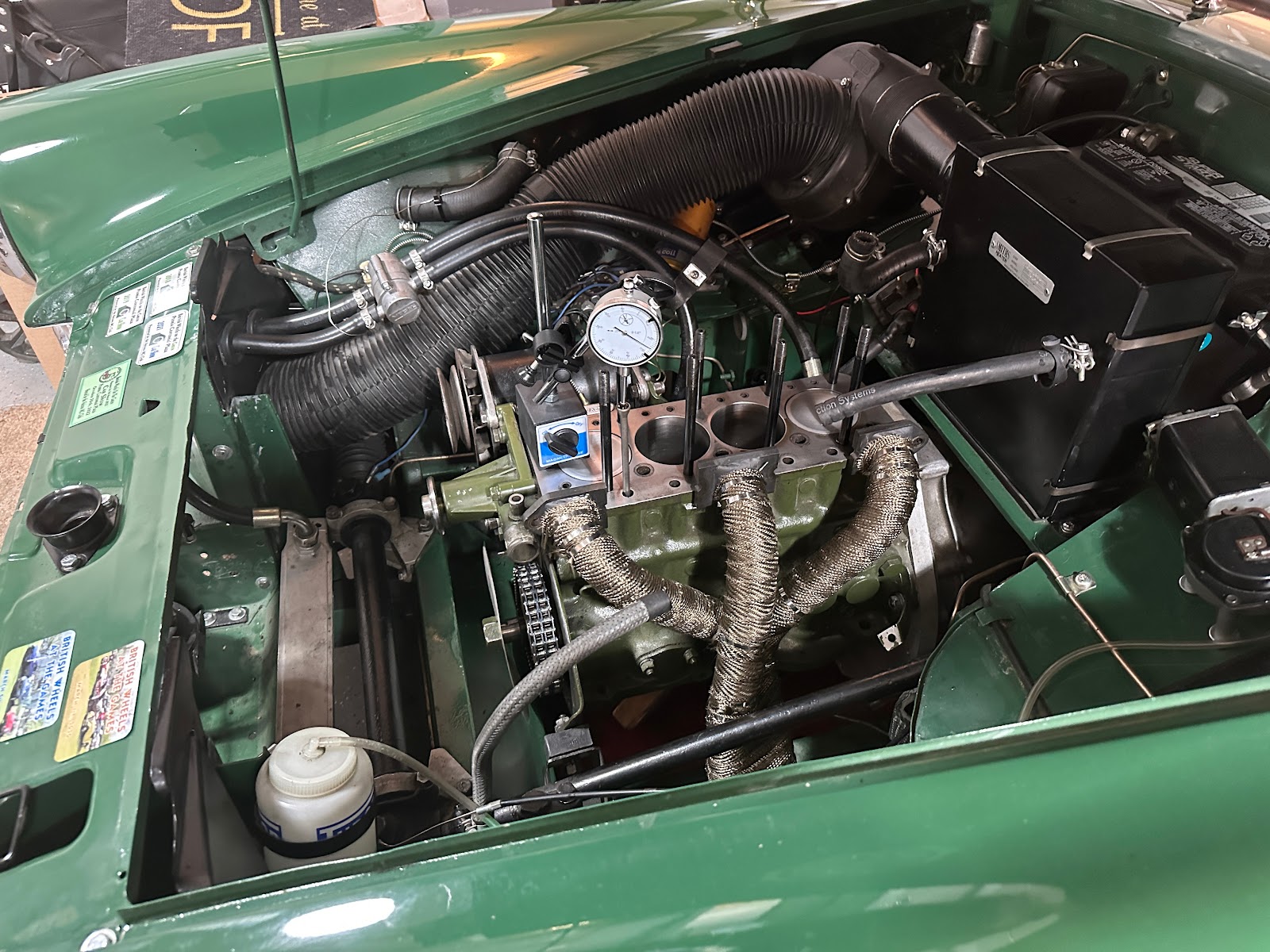
Now, I was in business.  I removed the timing cover to see my beautiful new gears and chain.

To remove the camshaft, the chain and gears have to come out.  In order to gain leverage I needed to stop the crankshaft from turning, so off came the oil pan and a piece of wood went in to a suitable spot.  And that's when I noticed something else.

If you look in the upper section of the photo, you will see where the oil pickup tube connects to the block.  You will also see that the nut that holds the pickup tube in place is completely unsecured.  No wonder I had wonky oil pressure!  The seal is a simple brass compression fitting, and without it being tightly held in place it will not be able to provide sufficient suction, and it won't hold a vacuum when the engine shuts down (aka the "prime" that keeps oil in the system ready to be pumped).

Score one for Team Me!  Believe it or not, that was a welcome sight.  It meant that my oil pump was not a source of failure.  That wasn't coming out without pulling everything out and apart, and I really, really didn't want to do that.

Getting back to the main point of this story... I was able to pull the gears and timing chain pretty easily, as one would hope.  (The camshaft nut is also a 1 5/16" socket.  Good thing I had another one.)

Before I went any farther, I pulled the distributor so I could pull the distributor drive, which is driven by the camshaft.

By the way, you might notice a switch where there shouldn't be one.  I installed a spin-on oil filter adapter, and so I no longer had a use for the light that comes on to indicate when the filter is clogged and being bypassed.  I converted it to a low oil pressure light.  It comes on when oil pressure is below 20psi, which is why I suspected something more than just the gauge for my wonky oil pressure problem.

I had reached the camshaft retaining plate.  It was time to employ a trick I learned online.

The problem with replacing a camshaft in an A-Series 1275 engine is that there are no side covers to gain access to the tappets (cam followers / lifters).  You are supposed to pull the engine, flip it over and do it the hard way.  But I read about some magicks that would let me do the job in situ.  The trick is to lift the tappets up and away from the cam lobes.  The tappets are made of metal.  Magnets stick to metal!  So I bought some 5mm neodymium magnets for a few bucks, and got some pot stickers out of the kitchen drawer.  I first superglued, then epoxied the magnets to the end of the sticks.  I now had a set of 8 remote tappet puller-uppers!

I took one, inserted it in the pushrod hole and lifted gently.  The tappet came up!  In fact, all 8 of them did.  I pulled them up and taped the sticks to the head studs, and the tappets were held out of the way.  Removing the sticks is easy - I just pull a bit harder and they (and the magnets) come right out.

With the tappets no longer an issue, I removed the camshaft retaining plate.  It was time for the big bravery test.  I said a short prayer to the gods of English motoring, and ever so gently removed the camshaft.  I needn't have worried - the cam came out easily and without fouling on the tappets.

I was elated.  I couldn't believe that worked so well!  I had to take a look underneath.  I almost wish I hadn't.

If you look at the tappets, they are held right where I wanted them.  But if you look at #6 (third from the right), you will see a horrible thing.  The tappet surface is completely destroyed.

That explains the tapping noise.  It sounds like valve #6 was sticking open a little long, causing the cam lobe to slam into the tappet and chew it up.  The lobe isn't in any better shape.

This cam is toast.

Well, I bought a camshaft, so I suppose I am happy that I have a real need to install it.  I have new tappets on order as well, but now I have to wait again.  I don't know why I didn't order them with the cam - you ALWAYS replace tappets with a new cam.  I guess I thought that such low miles on some fancy new tappets wouldn't have been a problem.  I thought wrong.

Here's the camshaft I bought.  It is an Evolution 001 from Mini Spares.  The specs look good, and the price was right.  It's cut from a new billet-steel blank and it's perfect.

I also bought forged Cooper S style rockers to match, as this cam doesn't work well with the 1.5 high lift rockers I have.  I had also bought a new shaft and had the original pedestals (heck, I've got a bag full) so that went together lickety-split.

So stay tuned for the next episode, when I put all of this back together!

More... »

Saturday, July 1, 2023

Carburetor Re-Rebuild

Well, it's been a while, hasn't it?

Lots has happened since we last spoke.  I finished Alice the MGB and both Alice and Gidget went to the 2022 BWOG.  They had a great time.  Juliette drove Alice and took third place in her class!  


Gidget took 6th in the Heritage class, which is a fair showing given I didn't really have time to prep her (because I worked up to the day before to get Alice ready).

So it was a great time.  Here are the two girls together after the show.  This is one of my favorite pictures.


Anyhow, this article isn't about that.  After the show, I noticed that Gidget had a ticking noise coming from her engine.  It had been getting worse, to the point where I stopped driving her.  So I finally broke down and pulled the cylinder head as I suspect the noise is a sticking valve.  I'll talk about that later.

Since I had the head off, of course the carbs had to come off too.  I figured I'd go ahead and go through them while I had the chance, to see how they've held up.  I have to say that they look good, but there was play around the throttle shafts that I didn't like.  So they came apart for inspection.

I took my handy bore gauge set and measured the throttle shaft bore in the carb body.  (You can get bore gauges for really, really small bores like this.)  And wouldn't you know it - they were actually out of round by .002".  The standard throttle shaft measures .248", and the bores measured a max of .254" on one carb and .252" on the other.  That's an air leak, folks.  It explains why it was so difficult to get Gidget to start without a lot of choke.

I had two options:

  • I could bore out the carb body and install bushings to return the clearance to standard;
  • I could bore out the carb body and install oversized shafts.
The HS2 carburetor does not have bushings for the throttle shaft.  Rather, the shaft rides directly on the aluminum body and is a sacrificial item.  The carb bodies don't really wear since brass is so much softer than aluminum - but almost 60 years meant there was a little, and it was enough.

I decided to go the oversize shaft route.  The shafts measure out at .258" (.010" oversize), and I confirmed that with my micrometer (which also confirmed that my mic was accurate).  That meant I needed a reamer.  Fortunately, I read a post that a 6.6mm reamer (.260") would work, and was available from Amazon for under $10.  Turns out they were right!

I also needed a vise that would hold the carb body.  Harbor Freight solved that for me, and I got a new tool.  I have a small bench top drill press that I was able to manipulate into being able to hold the vise and reach the other side of the carb body with the tip of the reamer.  Perfect.

I used the old throttle shaft as a guide to line up the carb body with the drill, and then swapped it for the reamer.

As Bob Ross would say, it was time for my bravery test.  I got some cutting fluid, turned on the press and slowly cut through the carb body.  And it worked.  I measured out the new bore at a nice round .261", which is a little more than I wanted but still okay.  And best of all, the new shaft fit like it was always there.  The alignment was perfect.


While I was busy patting myself on the back, I got another really good, but maybe bad idea.  I had seen a post on MGExp that talked about throttle shafts with O-rings installed.  I found those shafts, and I entertained buying them... but I already had two perfectly good new oversize shafts and that's what I committed to installing.  And yet, the idea beckoned... so I decided to really risk the biscuit and cut grooves for O-rings.

I practiced on the old throttle shafts, of course.  I have a kit of Viton O rings, and the A006 size is what I worked out I wanted.  The A006 is a .254" outer diameter ring and pretty thin.  Through trial and error, I found that cutting the throttle shaft to 0.148" would give me a completed outer diameter of .262", because the ring stretched a bit and thinned out once installed.

So more bravery tests for me... I marked out where the O rings needed to go.  I chucked the throttle shaft into the drill press, spun it up and with a thin file cut the grooves ever so carefully.  I first used a file with a sharp edge and slightly rounded back as it helped make a little clearance.  I followed that up with a flat, square edged file to smooth everything out.  This took quite a while and lots of measuring with my micrometer.  But I got there, fitted the O ring and it was precise.  I did the other side, and marveled at both my bravery and my work.

I lubed the O rings up with a bit of lithium grease and fitted the throttle shaft into the carb body.  It fit, first try!  I spun the shaft in the bore a number of times and it loosened up a bit, enough that I could spin it by hand with only slight resistance.  That's ideal.

After that, it was simply a matter of cleaning and reassembly.  And I was thrilled with the result.  There is no WAY that there can be an air leak now.  And all I need to do is replace the O ring for periodic maintenance.

I installed new throttle discs too, and everything's sealed up tight as a drum.  There's just the tiniest smidge of light coming through with the throttle fully closed. 


Of course, that was just one carburettor.  I had to do my bravery tests all over again for the second one.  But the second one turned out as pretty as the first.

All in all, it took me three hours including disassembly and reassembly.  I think Gidget's carbs will be good for a number of years.  Now I just need to get her cylinder head back, and installed, and everything put back together, and hope that the tick is no more.

More... »