Well, I know I said I'd have it all back together in this episode, but nah. I did make some progress.
Having extracted the cam and lifters, I took a closer look. Not good.
I decided that since I was already this far, I'd take a look at the main and rod bearings to judge if they had been worn due to my little cam problem and the lack of oil pressure at startup. I pulled the center main bearing, and while they aren't "bad", they aren't great either. I see a little bit of stuff. It could be much worse.
You can see some wear in a couple of spots. The crank journal looks okay, though.
The $64,000 question was how I was going to get the bearing out with the crankshaft in place. I tried a popsicle stick, but it didn't have enough flexibility to be able to push the bearing shell all the way around. But I did have bearing shells... the ones I was removing! So I cut one down carefully and filed the end. This gave me about 1/4" of room to be able to push on the shell (with a wooden dowel) and spin the old shell right out. It worked a treat. Then, I lubed up the journal and bearing and rotated the new bearing into position, which pushed my cut-down bearing shell back out and into my hand.
I was only able to get to the front and center main bearings. The rear main bearing cap is trapped by the rear plate where the transmission is, and I wasn't able to maneuver it out of the way. So that bearing has to stay until I pull the engine someday. But given the other two bearings weren't significantly worn, I'm gonna have to be okay with that.
Replacing the big end (rod) bearings was pretty easy. That's as simple as removing the cap, pushing the piston and rod up enough to move the crank out of the way, and popping the bearing shell out. Putting it back is about as easy. It's not THAT easy to do while lying on your back, but it wasn't bad.
Once they were all replaced, I gave them a once-over and wasn't terribly disappointed. There is wear, more than I like, but there are no streaks or gouges indicating metal was trapped in the bearings. So I feel better. Hopefully solving my oil prime issue will minimize this problem in the future.
Once the bearings were in place, I bolted up and tightened(!) the oil pickup.
I then cleaned the pistons and bores to remove the excessive carbon buildup I found.
Ooh, shiny!
With the bottom end basically complete, it was time to time the camshaft. "Timing a camshaft" or "degreeing a camshaft" means determining the angles at which the valves open and close and making sure they match the manufacturer's specifications and/or recommendations. For the cam I installed, Mini Spares recommends the LCA (Lobe Centerline Angle, or the spot where the intake valve is fully open at maximum lift) to be 107 degrees. Engines typically have this value between 102 and 110 degrees. An earlier opening (retarded, which ironically is a larger number) gives a little more push at lower revs, and a later opening (advanced, opening earlier) moves the power band upward. But there are limits, so knowing what the manufacturer wants matters.
The way to degree a camshaft is relatively straightforward after you do this a couple of times:
- Put the #1 piston roughly at TDC so you can install the timing gears.
- Install the timing gears, with the manufacturer's timing marks as close to aligned as possible.
Usually there are indentations on each gear, so it's also known as 'lining up the dots'.
- Install a degree wheel. A degree wheel provides the angles at which events (like a valve opening) occur relative to TDC.
- Install a pointer and line it up so that the pointer points to the degree wheel at TDC (0 degrees).
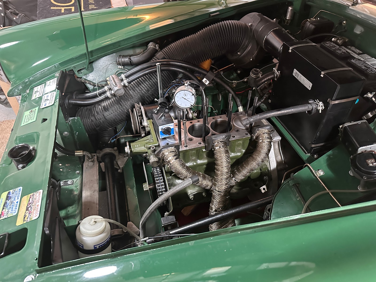
- Find "true TDC". To find TDC, you need to figure out exactly when the piston is moving from its upward to its downward motion. To do this with the cylinder head removed, you need a dial indicator that measures in small increments and a stand to hold it securely in place. Here, I am already setting it up to measure valve lift. To measure TDC, get the indicator's pointer to rest lightly upon the #1 piston and zero out the dial.
- Rotate the crankshaft back and forth until you see the maximum value for the piston's height. Zero the dial at that value.
- Rotate the crankshaft back until the indicator shows a drop of some value (like -.020") and mark the value on the degree wheel.
- Rotate the crankshaft forward until the same reading is found, and mark the value.
- Split the difference between the two values. For example, if the values are 6 and -8, the total would be (6 + (-8)) = -2, and the true value would be half that at -1 degrees.
- Adjust the degree wheel. In this case, I adjusted it back by one degree. When I brought the crankshaft back to TDC, the pointer showed 0.
- Once TDC is found, find the LCA. This is done by finding where the #1 intake valve reaches maximum lift. To find maximum lift, you need a pushrod installed in the lifter hole for the #1 intake valve and your dial indicator set up like the picture above. The pointer of the indicator rests in the cup of the pushrod.
- Rotate the crankshaft until the indicator reaches its lowest reading. This happens to be when the valve is closed. Zero the dial.
- Rotate the crankshaft clockwise and watch the dial spin until it reaches its maximum value. Note this as your intake valve lift and compare to spec. My spec indicated .264" of lift, and I measured exactly .264". Zero the dial and note the reading on the degree wheel for reference. This will be close to the final value, but not exact. There are a couple of degrees where the lift value won't change, but the angle will.
- Rotate the crankshaft counterclockwise past -0.050" on the dial, and then forward until the dial reads -0.050". Since the engine turns clockwise, rotating backward, then forward removes any slop from the timing chain. Mark the value on the degree wheel.
- Rotate the crankshaft forward until the dial reads +0.050". Mark the value.
- Add the numbers and divide by 2. In my case, the values were 58 and 151. My result is (58 + 151) = 209 / 2 = 104.5. That is the true LCA as measured. My initial rough reading was 105, so it was pretty close.
- You probably want to do this a couple of times to compare values.
- Since I am looking for 107 degrees as my LCA value, I need an offset key which allows the camshaft timing gear to be rotated a tiny bit to either retard or advance the timing. You can get offset keys in degree increments. Since I can't get a half-degree of offset, I went with a 2 degree offset key. That will retard the timing just a tad, which moves my powerband down a bit and that's where I want it.
And that's as far as I got. I'm waiting for the offset key. Once I have it, I'll install it and retime to verify I am at an LCA of 107-ish degrees. Then I'll bolt in the cam timing gear, button up the sump, and reinstall the oil thrower, timing chain cover and crank pulley. That will finish off the bottom end rebuild.
Then, I'll move to the top end...