Monday, September 9, 2024

Dy-No-Mite

I had a good reason to clean up the engine bay.  (Oil everywhere will do that.)  It was easiest to remove the generator to get to the bits that were underneath.  I figured, "Well, it's out... let's take a look."

Lucas C39/C40 dynamos (generators to us Yanks) are pretty simple devices.  I've rebuilt this one already, and it was working fine... aside from slightly low voltage output at idle.  It was also making a bit of noise at the rear bushing, which I figured was probably on its way out.  I had not replaced it.

Here's the complete teardown of the dynamo.  Teardown isn't difficult.  The hardest part is using a small puller to separate the armature from the front plate's bearing.

I could see something I didn't like.  The armature rear spindle is really scored.  It wasn't this bad a few years ago, but there was wear.

A little research on the Googles shows these are readily available.  Since C39/40 dynamos were used in everything in the 50s and 60s, even farm tractors (!), I found a replacement armature at a tractor supply store for $75, and brushes for $12.

The new armature is a nearly perfect fit dimensionally, being just a tad longer at the rear spindle.

I also ordered a new rear bushing.

Replacing the rear bushing isn't difficult, but takes a bit of care.  Knocking the old one out was as easy as getting a thin screwdriver between the bushing and the housing, and then pulling it out with a needle nosed plier.  (It was a LITTLE harder than that, but the bushing is copper and will bend/split with some persuasion.)

The bushing is actually three elements: a felt pad that holds oil, a retaining plate for the felt pad, and the bushing itself.  The pad goes in first, followed by the plate (with the concave side toward the back), then the bushing.  The retaining plate has little slots in it to let the oil ooze past it and onto the bushing.

Driving the new bushing in in was a bit of a chore.  I sanded the outside of the bushing down a tad to get its outer diameter closer to the inner diameter of the hole, and then put the bushing in the freezer before tapping it into place.

Once in, I had to gently ream the bushing out a bit to gain enough clearance for the new armature to spin freely.  I also slightly modified the rear spindle on the armature to make it a tiny bit shorter and gave it a taper to clear the retaining plate.  This took some trial and error and a few test fittings to get right.

After all that, I filled the bushing with oil and let it soak down, repeating a couple of times over the course of a day so the bushing had a chance to soak up oil.  I had soaked the bushing before as well.

Reassembly is straightforward.  The armature goes back into the front plate, then is assembled to the main body, followed by installing the rear plate.  There is a trick to installing the new brushes:  Install the brushes, and push the retaining spring to the side of each.  That holds the brushes apart so the rear plate can be installed to the armature and body.  Then, flip the little springs to have them push on the back of the brush.  This makes a real chore take about 30 seconds.

After some paint, she's done.  Spinning by hand makes a couple of tenths of a volt, so I am pretty sure it's going to work.


I painted the generator body green as that is what it should be on a '65 (I had painted it black).  I painted the pulley and fan black, even though they should be metal, just because I wanted to.  I think it looks great.

Hopefully, that's a job done for another few decades.  With regular oiling, it should last a long time.

More... »

Where's that Oil Coming From?

I went for a short drive a couple of weeks ago, and Something Happened.

It wasn’t long, just up the road a ways to the gas station to get an ICEE. When I pulled out of the parking lot, I saw some oil on the ground. I thought, “Boy, someone’s losing a lot of oil.” (I’m no Joe Friday.) “It’s not me, though.”

Oh, but guess who it was. It WAS me. I got home, pulled into the garage and saw a trail of oil following me home.

It happens that the oil pressure gauge line cracked and sent a quart or so of fresh, clean Castrol all over the inside of the engine bay and down to the road.

Well, it’s an easy fix, at least. Parts are on the way and everything’s clean again. So, she’ll wait a week or so.

More... »

Tuesday, February 20, 2024

Cutting and Buffing and Bears, Oh My!

Well, it was bound to happen eventually.  Someone gave me a little tap a couple of weeks ago, and I ended up with some damaged paint and chrome.  Nothing serious, but frustrating...

I had to fix two major spots: One on the driver's side of the bonnet and one around the passenger's side headlamp.  The paint cracked, and if left unrepaired would eventually flake and be prone to rust.  And I knew it was there.

Along with a new grille and chrome surrounds, and a new turn indicator lens, the only damage was to Gidget's pride.  And paint.

So we fixed it!

Here's what needed fixing.  It doesn't look like much, but there was quite a bit of work involved to do it right.

Like I said, not too bad.  But to fix it means removing all the damage... which in this case went down to the metal.

We ("we" is me and my friend Mike) started by removing the grille and surrounds, turn indicator and headlamp, and mirrors and antenna.  Mike decided that the only way to fix the cracked paint on the wing was to re-clearcoat the whole thing, otherwise there would be a blend line that would be visible.  Then, he sanded out the cracked filler on the bonnet and reapplied a lightweight filler.  After a coat or two of primer, it was smooth and invisible (aside from the color, that is).  He also sanded down the crack on the wing and was able to primer without a need for filler.


Once dry and sanded, we sanded the clearcoat on the bonnet and fender.  He taped off the parts that didn't need paint and made the problem go away.

Now watch this.  Coat by coat, the problem area disappears.  He wiped with a tack cloth in between each coat.

Then he applied three coats of clear...


Wow.

After drying, the fun part began.  That's the subject of this article, actually--the fun of color sanding, cutting and buffing the finish.

Color sanding is the art of taking a perfectly good looking finish and making it look even better by first making it look terrible.  You actually sand your beautiful looking clear coat to get rid of all the imperfections - "orange peel" and "fisheyes".  Do do this, you need sandpaper in increasingly fine grit (starting at 1000), and an orbital sander.  I prefer a "palm sander" as it is easy to control the pressure and speed. 

I started with 1000 grit and lightly worked the surface to remove some orange peel and get things very smooth.  I used slow, steady passes with the sander running at a moderately slow speed.  From there, I went to 3M Trizact pads in grits of 1500, 3000, and 5000.  Trizact pads are to be used damp, so I lightly misted the surface each time and wiped clean in between.

At each stage, I lightly went over the surface until I covered the whole area.  The finish gradually improved until after the pass at 5000 grit, there was actually a hazy shine.  5000 grit is almost like using copy paper as sandpaper.


Once sanding was done (and I did go back a few times to correct more things), it was time to "cut".  Cutting is the application of a compound to start removing the scratches left by sanding.  Here's a couple of shots halfway through a pass to show how quickly the finish improves.  I started by using a wool pad, then followed with a pass using a foam pad designed for use with compound.  I used Meguilar's products for this stage.

Once the passes with the compound were done, I moved to "buffing" with a polish.  You can't really tell too much from these photos, but under brighter light you can see the scratches disappear.

Finally, I finished with a very fine 3M polishing compound and then some Griot's Garage spray wax.

I wrapped up by reinstalling all the chrome surrounds and mirrors, and a new grille from AH Spares.  I treated Gidget to new mirrors and some fancy bumperettes from a Bugeye Sprite.  I made custom brackets and installed a pair in the front, too.  I think she looks sharp!


I call her my tiger cub. :)

I did find a bunch of things to fix, since I am not super skilled at this.  I'll fix 'em.  It's not hard and really is mostly a need for good lighting to be able to see the flaws at the time.  The first time I did this during initial assembly, it took me a week.  This was a few hours.  I'm still very happy and Gidget is better than ever!


More... »

Tuesday, December 19, 2023

Camshaft IV

I know it's been a while... again... but I did finish this!

Once I got the cam timing set, it was just a matter of reassembly.  But I did a little extra cleanup on the intake manifold too.  

Per Vizard's book:

Being aluminum and having a spare made this an easy job.


I've already done all the other tricks rto the carb bodies themselves.  Once of these days I need to have a flow test done.

Okay, on to reassembly!

So I'd love to be able to say that was the end of the saga.  But you know the answer to that.

The first problem showed up when I went to start up.  I couldn't get her to start.  I tried checking timing and fuel, but no dice.

Then, I heard a horrible squealing noise when I went to start.  I thought I had done Something Really bad inside the engine.  Fortunately, it wasn't that bad.  The starter bendix hung up and stayed engaged.


I got it unstuck for the time being, but I did end up replacing it with a high torque starter (which works great!) from a 1989 Isuzu Trooper II.  It is a direct fit replacement with no modification required.

Finally, I get the timing set right and she started!  She sounded great and oil pressure came up immediately... but I noticed that the oil pressure was low, like 50psi instead of the 70-80 I expected.  I finished the 20 minute break-in and shut her down, and went to think.  And I had a horrible thought.  I went to look at the main bearings I removed.  The back of the bearing read ".010".  I put in standard size bearings.

Aw, come on!

So that meant I had to do the job over again, except for removing the cam from the block.  It didn't take a ton of time, and I had the whole 'swap bearings in block' routine down pretty well.  It just hurt my pride to have to disassemble what I had spent so much time painfully reassembling.

In the end, post-swap oil pressure came up to 75psi and stayed there.  After another break-in period, I went for a drive.  And wow.  Gidget's got some guts now!  She pulls strongly and really takes off at 3000 RPM.

I've put about 500 miles on her since I finished the work (and went to the 2023 BWOG!), and she still runs amazingly well.  Oil pressure comes up immediately and I have 60psi at hot idle.  She is a little clattery until she warms up, but the sounds of a self destructing camshaft is gone.

And you might notice a little extra bling... she's worth it.


Life is good once again. 

More... »

Monday, August 21, 2023

Camshaft Replacement III: The Search for More Power

LLAP...

I'm getting there.  I was just waiting for this.


This little bugger cost way too much.  But I had to have it, to set up the cam properly.  It is an 'offset key' that shifts the engagement of the camshaft by 2 degrees.

Anyhow, that's done.  I installed the key and rechecked the timing as I described in my last post.  This time, I got (61 + 153) = 214 / 2 = 107.  That's spot on. I'm within a degree and that's good enough for what I can do.

I buttoned up the sump, installed the oil thrower and timing cover and crank pulley, and the bottom end is complete.


And I cleaned, too!

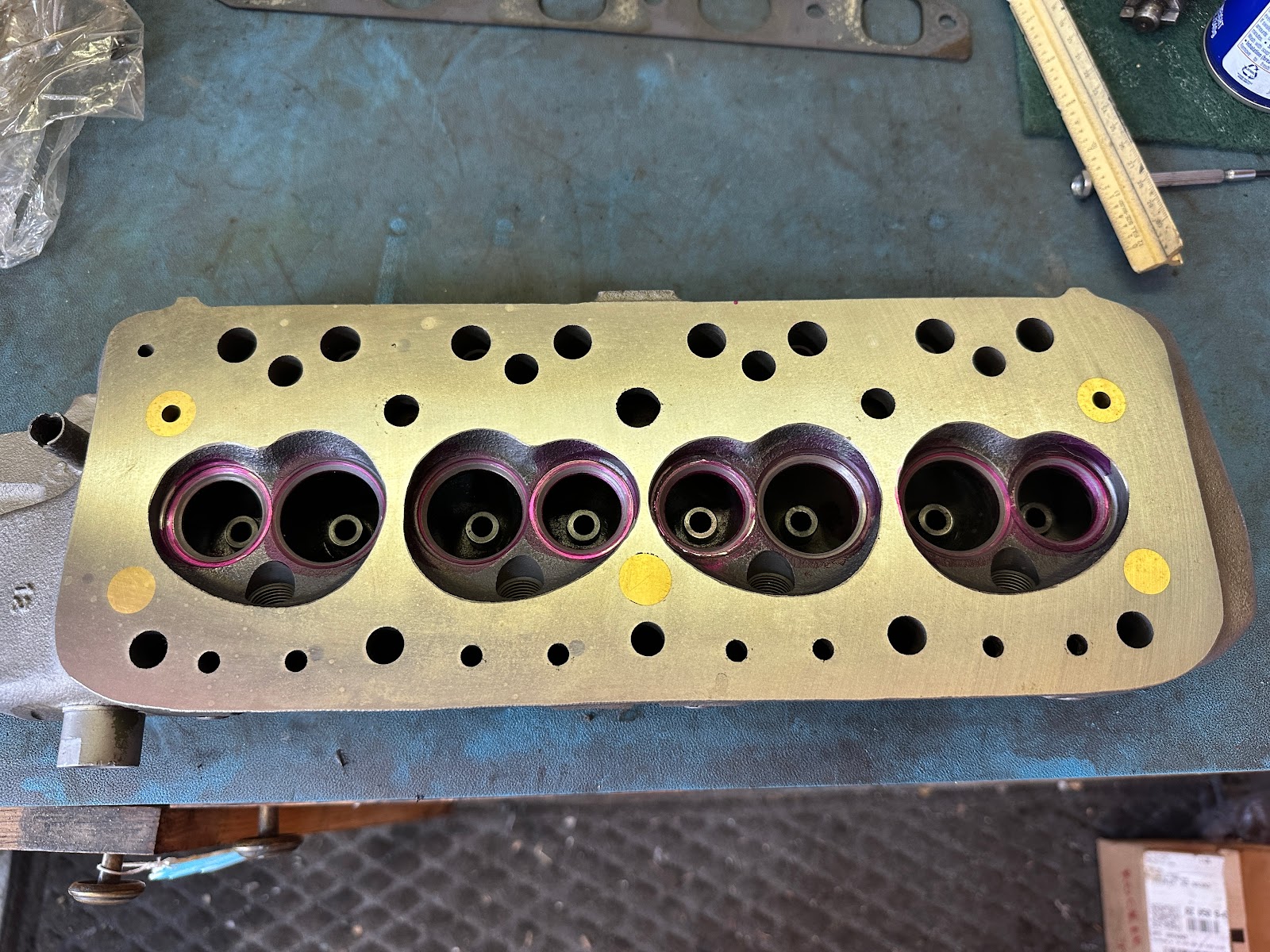
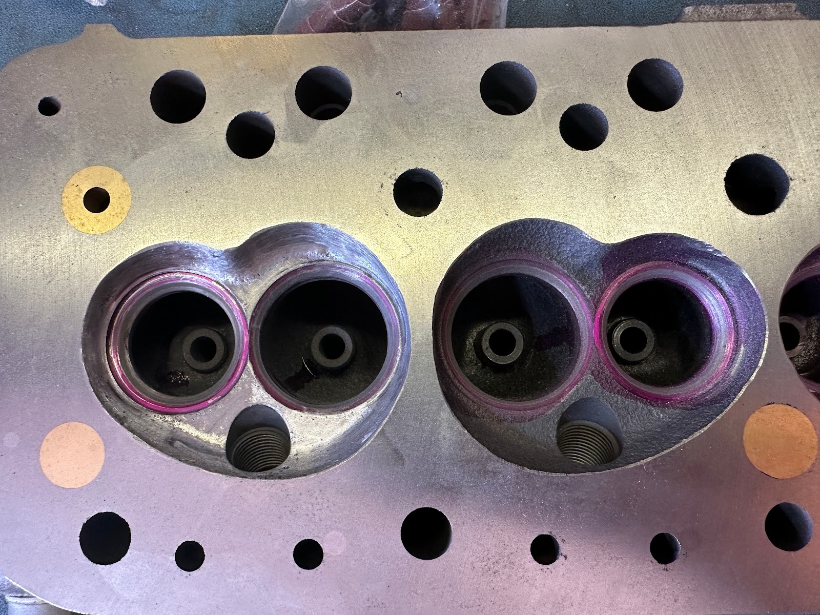
After a short celebratory rest, I turned my attention to the head.  My plan was to polish the combustion chambers, and port and polish the exhaust ports.  I intend to leave the intake ports alone because they already match the diameter of the intake manifold, and I have read that a little 'swirl' (turbulence) is helpful to mix up the intake charge.  Maybe I'm full of it, but that's my story and I'm sticking with it.

Here's the head before I did anything.


Nothing special, right?  Right.

All I did was spend a lot of time with near-infinite patience to gently polish the combustion chamber surfaces to be as smooth as I could get without going mad.  I think I did okay.  I used a small tapered grinding stone and some cylinder and cone-shaped sanding tubes.  I think I got away with it.  I did not appreciably increase the size of the combustion chamber.  Here's a comparison:

And the final result:

Who knows if it will help things.

The real gain I intended to reap was in the exhaust ports.  The port openings are significantly smaller than the manifold's openings as evidenced by the buildup on the manifold gasket.  So I got to work with that tapered grinding stone.  I managed to open things up quite a bit without screwing things up.  After the grinding stone, I used those tapered cylinders up to 240 grit to smooth things out.  Exhaust is one area where you do NOT want swirl; it will slow the exiting gases and you want them to leave quickly. 

Here's a before and after comparison.  The blue marks are where the gasket is larger than the port (and mot matched), and that's what I opened up.

I think that's a lot.  I had to be careful not to break through to the pushrod holes, because that would have been A Bad Thing.

Here's the finished product.


I painted the head after cleaning all the gunk out from the porting process.

All that remains is to assemble the valves to the head and start putting big pieces together!
More... »

Wednesday, August 16, 2023

Camshaft (And Other Things) Part Deux

Well, I know I said I'd have it all back together in this episode, but nah.  I did make some progress.

Having extracted the cam and lifters, I took a closer look.  Not good.

I decided that since I was already this far, I'd take a look at the main and rod bearings to judge if they had been worn due to my little cam problem and the lack of oil pressure at startup.  I pulled the center main bearing, and while they aren't "bad", they aren't great either.  I see a little bit of stuff.  It could be much worse.

You can see some wear in a couple of spots.  The crank journal looks okay, though.

The $64,000 question was how I was going to get the bearing out with the crankshaft in place.  I tried a popsicle stick, but it didn't have enough flexibility to be able to push the bearing shell all the way around.  But I did have bearing shells... the ones I was removing!  So I cut one down carefully and filed the end.  This gave me about 1/4" of room to be able to push on the shell (with a wooden dowel) and spin the old shell right out.  It worked a treat.  Then, I lubed up the journal and bearing and rotated the new bearing into position, which pushed my cut-down bearing shell back out and into my hand.

I was only able to get to the front and center main bearings.  The rear main bearing cap is trapped by the rear plate where the transmission is, and I wasn't able to maneuver it out of the way.  So that bearing has to stay until I pull the engine someday.  But given the other two bearings weren't significantly worn, I'm gonna have to be okay with that.

Replacing the big end (rod) bearings was pretty easy.  That's as simple as removing the cap, pushing the piston and rod up enough to move the crank out of the way, and popping the bearing shell out.  Putting it back is about as easy.  It's not THAT easy to do while lying on your back, but it wasn't bad.

Once they were all replaced, I gave them a once-over and wasn't terribly disappointed.  There is wear, more than I like, but there are no streaks or gouges indicating metal was trapped in the bearings.  So I feel better.  Hopefully solving my oil prime issue will minimize this problem in the future.


Once the bearings were in place, I bolted up and tightened(!) the oil pickup.

I then cleaned the pistons and bores to remove the excessive carbon buildup I found.

Ooh, shiny!

With the bottom end basically complete, it was time to time the camshaft.  "Timing a camshaft" or "degreeing a camshaft" means determining the angles at which the valves open and close and making sure they match the manufacturer's specifications and/or recommendations.  For the cam I installed, Mini Spares recommends the LCA (Lobe Centerline Angle, or the spot where the intake valve is fully open at maximum lift) to be 107 degrees.  Engines typically have this value between 102 and 110 degrees.  An earlier opening (retarded, which ironically is a larger number) gives a little more push at lower revs, and a later opening (advanced, opening earlier) moves the power band upward.  But there are limits, so knowing what the manufacturer wants matters.

The way to degree a camshaft is relatively straightforward after you do this a couple of times:

  1. Put the #1 piston roughly at TDC so you can install the timing gears.
  2. Install the timing gears, with the manufacturer's timing marks as close to aligned as possible. 
    Usually there are indentations on each gear, so it's also known as 'lining up the dots'.


  3. Install a degree wheel.  A degree wheel provides the angles at which events (like a valve opening) occur relative to TDC.
  4. Install a pointer and line it up so that the pointer points to the degree wheel at TDC (0 degrees).
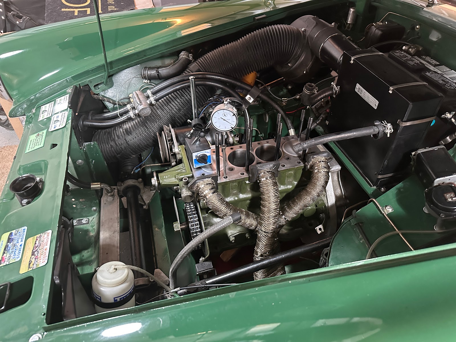
  5. Find "true TDC".  To find TDC, you need to figure out exactly when the piston is moving from its upward to its downward motion.  To do this with the cylinder head removed, you need a dial indicator that measures in small increments and a stand to hold it securely in place.  Here, I am already setting it up to measure valve lift.  To measure TDC, get the indicator's pointer to rest lightly upon the #1 piston and zero out the dial.


    • Rotate the crankshaft back and forth until you see the maximum value for the piston's height.  Zero the dial at that value.
    • Rotate the crankshaft back until the indicator shows a drop of some value (like -.020") and mark the value on the degree wheel.
    • Rotate the crankshaft forward until the same reading is found, and mark the value.
    • Split the difference between the two values.  For example, if the values are 6 and -8, the total would be (6 + (-8)) = -2, and the true value would be half that at -1 degrees.
    • Adjust the degree wheel.  In this case, I adjusted it back by one degree.  When I brought the crankshaft back to TDC, the pointer showed 0.
  6. Once TDC is found, find the LCA.  This is done by finding where the #1 intake valve reaches maximum lift.  To find maximum lift, you need a pushrod installed in the lifter hole for the #1 intake valve and your dial indicator set up like the picture above.  The pointer of the indicator rests in the cup of the pushrod.
    • Rotate the crankshaft until the indicator reaches its lowest reading.  This happens to be when the valve is closed.  Zero the dial.
    • Rotate the crankshaft clockwise and watch the dial spin until it reaches its maximum value.  Note this as your intake valve lift and compare to spec.  My spec indicated .264" of lift, and I measured exactly .264".  Zero the dial and note the reading on the degree wheel for reference.  This will be close to the final value, but not exact.  There are a couple of degrees where the lift value won't change, but the angle will. 
    • Rotate the crankshaft counterclockwise past -0.050" on the dial, and then forward until the dial reads -0.050".  Since the engine turns clockwise, rotating backward, then forward removes any slop from the timing chain.  Mark the value on the degree wheel.
    • Rotate the crankshaft forward until the dial reads +0.050".  Mark the value.
    • Add the numbers and divide by 2.  In my case, the values were 58 and 151.  My result is (58 + 151) = 209 / 2 = 104.5.  That is the true LCA as measured.  My initial rough reading was 105, so it was pretty close.
    • You probably want to do this a couple of times to compare values.
  7. Since I am looking for 107 degrees as my LCA value, I need an offset key which allows the camshaft timing gear to be rotated a tiny bit to either retard or advance the timing.  You can get offset keys in degree increments.  Since I can't get a half-degree of offset, I went with a 2 degree offset key.  That will retard the timing just a tad, which moves my powerband down a bit and that's where I want it.

And that's as far as I got.  I'm waiting for the offset key.  Once I have it, I'll install it and retime to verify I am at an LCA of 107-ish degrees.  Then I'll bolt in the cam timing gear, button up the sump, and reinstall the oil thrower, timing chain cover and crank pulley.  That will finish off the bottom end rebuild.

Then, I'll move to the top end...
More... »